
UHF Duplexer Project
The motivation here is to save the installation of a cable within the home.When built, my house was installed with a single coaxial drop cable from the loft to the lounge, carefully hidden in the cavity wall. This cable carries the DVB TV channels from the roof antenna to the TV in the lounge. I also have a cable TV box in the lounge that I would like to distribute around the house and the distribution amp is best placed in the loft for easy access to all rooms. Therefore, a Duplexer at either end of the drop cable will allow it to carry DVB-TV down the coax and Cable-TV up the coax concurrently, providing I select a suitable Frequency for the Cable-TV distribution.
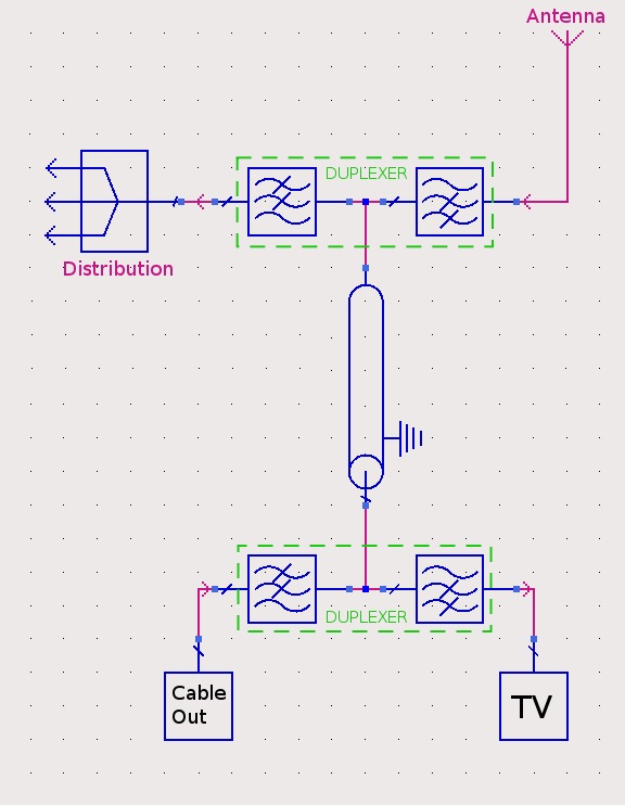 The TV Multiplexes begin at 739MHz and extend up to 800MHz. The Cable-TV distribution is programmable from 471-860 MHz.
I will thus implement a low-pass section to carry the CableTV up the coax at ~488MHz and a high-pass section to carry the DVB-TV down.
The low pass section will also carry DC to power the distribution amp in the loft and Magic-eye remote control codes back down the Cable-TV box.
The TV Multiplexes begin at 739MHz and extend up to 800MHz. The Cable-TV distribution is programmable from 471-860 MHz.
I will thus implement a low-pass section to carry the CableTV up the coax at ~488MHz and a high-pass section to carry the DVB-TV down.
The low pass section will also carry DC to power the distribution amp in the loft and Magic-eye remote control codes back down the Cable-TV box.In summary, the specifications are:
*DC - 530MHz (covering UHF ch21-ch28) < 2dB Insertion Loss
*710- 860MHz (covering UHF ch50-ch68) < 2dB Insertion Loss
*Rejection of 488MHz for the high pass section >40dB
*All ports to have return losses >10dB
Equations exist for the calculation of duplexer poles, but for this basic application, the design process can be simplified.
1) Determine the number of filter poles to ensure we exceed the rejection requirements.
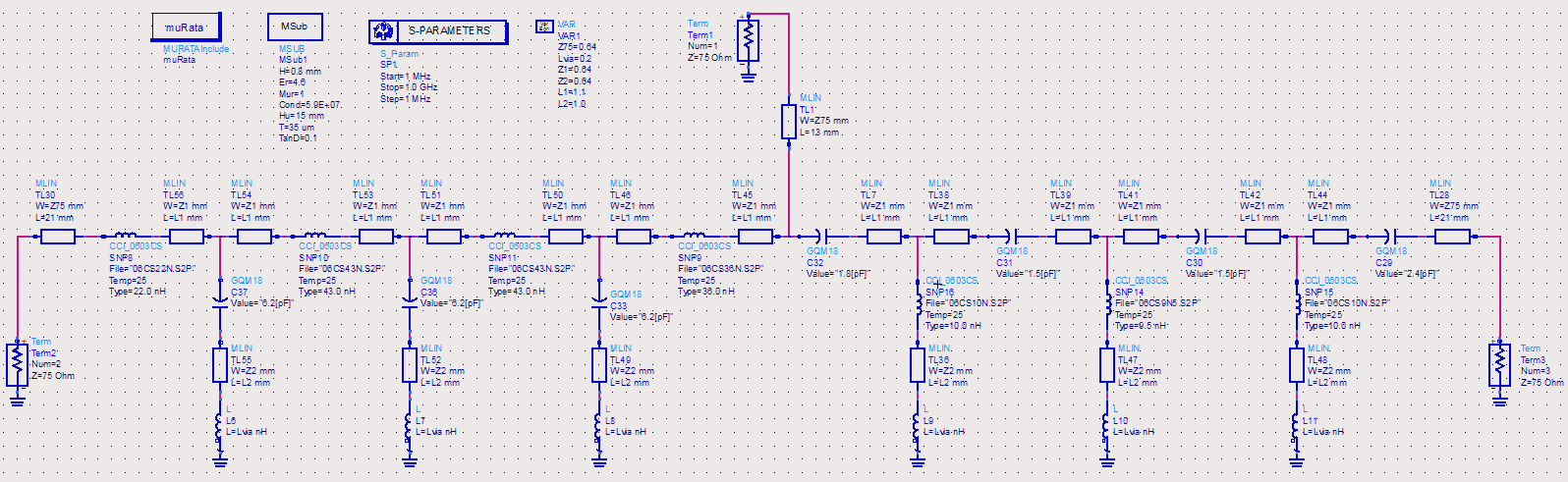
2) Use the Low-Pass and High-Pass filter designers on the RF-tools tab to calculate ideal filters.
3) Using a simulator, join them together and tweak the first couple of poles either side of the common port to tune the duplexer.
4) Add in microstrip lines/vias and re-tune.
5) Construct the PCB.
6) Populate the PCB and test, re-tune if necessary.
 The degree of precision to real implementation in the simulation depends upon application, frequency, components etc.
Based on experience, this simulation should suffice in a reasonably accurate model with little need for tuning once built.
The degree of precision to real implementation in the simulation depends upon application, frequency, components etc.
Based on experience, this simulation should suffice in a reasonably accurate model with little need for tuning once built.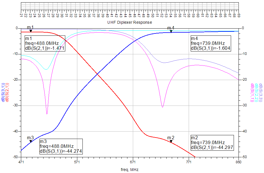 The simulation results show that the insertion loss, rejection & return loss specifications have been met.
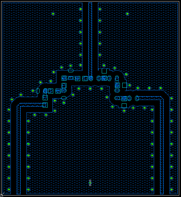 The PCB was exported as a Gerber and milled using a table-top milling machine and populated by hand.
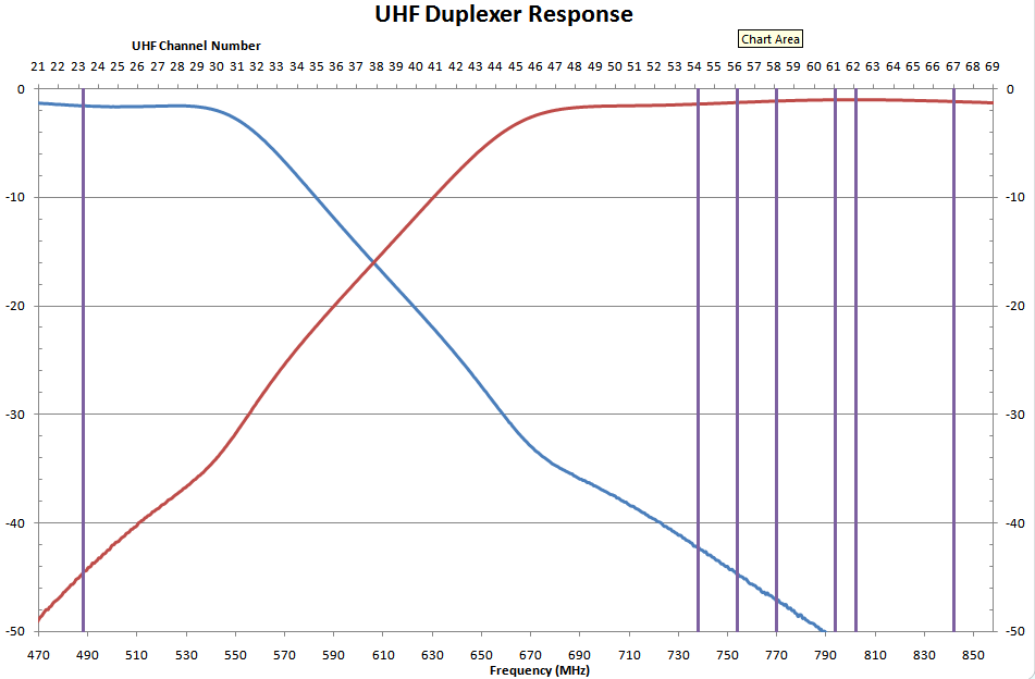 The measured results of the constructed circuit show slight deviation from the simulation, but not enough to warrant re-tuning. All design goals have been met with sufficient margin.
The Cable-TV output and DVB multiplex frequencies are shown by the purple vertical lines.
Note: The measured data is that of the finished boxed-up circuit, connectorised with F sockets.